The data link control (DLC) fiber distributed data interface (FDDI) device manager supports the logical link control (LLC) protocol and state tables described in the Token-Ring Network Architecture Reference, which also contains the local area network (LAN) IEEE 802.2 LLC standard. Both address-resolve services and name-discovery services are supported for establishing remote attachments. A direct network interface is also supported to allow users to transmit and receive unnumbered information packets through DLC FDDI without any protocol handling by the data link layer.
A combined station is supported for a balanced (peer-to-peer) configuration on a logical point-to-point connection. This allows either station to initiate asynchronously the transmission of commands at any response opportunity. The sender in each combined station controls the receiver in the other station. Data transmissions then flow as primary commands, and acknowledgments and status flow as secondary responses.
Both asynchronous disconnect mode (ADM) and asynchronous balanced mode extended (ABME) are supported. ADM is entered by default whenever a link session is initiated. It switches to ABME only after the set asynchronous balanced mode extended (SABME) packet sequence is complete by way of the DLC_CONTACT command or a remote-initiated SABME packet. Once operating in ABME, information frames containing user data can be transferred. ABME then remains active until the LLC session ends, which occurs because of a disconnect (DISC) packet sequence or a major link error.
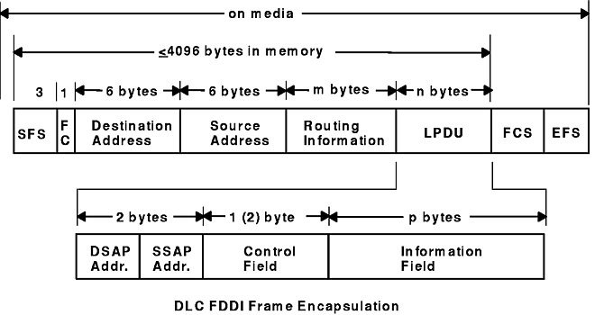
All communication between a local and remote station is accomplished by the transmission of a packet that contains FDDI headers and trailers, as well as an encapsulated LLC link protocol data unit (LPDU). The DLC FDDI Frame Encapsulation figure describes the FDDI data packet.
Figure 1-8. DLC FDDI Frame Encapsulation. This diagram shows the FDDI data packet containing the following: SFS (3 bytes), FC (1 byte), destination address (6 bytes), and source address (6 bytes), routing information (m bytes), LPDU length (n bytes), FCS, and EFS. Another line shows that LPDU consists of the following: DSAP address, SSAP address (together with DSAP address consist of 2 bytes), control field [1 (2) byte], and the information field (p bytes).
The FDDI data packet consists of
the following:
Notes:
- SFS, FCS, and EFS are added and deleted by the hardware adapter. Three bytes of alignment always precede the FC field when located in memory buffers.
- The maximum byte length of a transfer unit has been set to 4096 bytes to align to the size of an mbuf cluster (where a transfer unit is defined as fields FC through LPDU, plus a three-byte front alignment pad).