The Standard Ethernet data link control (DLCETHER) supports the systems network architecture (SNA) logical link control (LLC) protocol and state tables as described in the Token-Ring Network Architecture Reference, which also contains the local area network (LAN) IEEE 802.2 LLC standard. Additional direct-name services have been added for establishing remote connections.
A combined station is supported for a balanced (peer-to-peer) configuration on a logical point-to-point connection. Either station can asynchronously initiate the transmission of commands at any response opportunity. The data source in each combined station controls the data sink in the other station. Data transmissions then flow as primary commands, and acknowledgments and status flow as secondary responses.
Both asynchronous disconnect mode (ADM) and asynchronous balanced mode extended (ABME) are supported. ADM is entered by default whenever a link session is initiated, and is switched to ABME only after the set asynchronous balanced mode extended (SABME) command sequence is complete. Once operating in ABME, information frames containing user data can be transferred. ABME then remains active until the LLC session ends, which occurs because of a disconnect (DISC) command sequence or a major link error.
All communication between a local and remote station is accomplished by the transmission of a packet that contains the Ethernet headers and trailers and an encapsulated LLC protocol data unit (LPDU). This packet format is specifically designed for the SNA protocol, but other protocols can use this format as well.
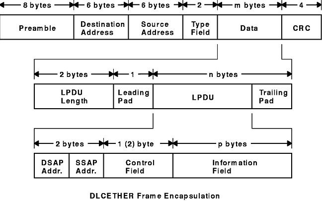
The DLCETHER Frame Encapsulation figure illustrates the Ethernet data packet.
Figure 1-7. DLCETHER Frame Encapsulation. This diagram shows the Ethernet data packet. The first line contains the following: preamble (8 bytes), destination address (6 bytes), source address (6 bytes), and type field (2 bytes), data (m bytes), CRC (4 bytes). The second line defines data as including the following: LPDU length (2 bytes), leading pad (1 byte), LPDU, and the trailing pad (which together with the LPDU equal n bytes). The third line shows that LPDU consists of the following: DSAP address, SSAP address (together with DSAP address consist of 2 bytes), control field [1 (2) byte], and the information field (p bytes).
The Ethernet data packet consists
of the following:
Note: The Preamble and CRC identify both of these as something that is added and deleted by the hardware adapter.