The token-ring data link control (DLCTOKEN) device manager operates between two or more nodes on the token-ring local area network (LAN) using IEEE 802.2 procedures and control information as defined in the Token-Ring Network Architecture Reference. Protocol support includes:
DLCTOKEN provides full-duplex, peer-data transfer capabilities over a token-ring LAN. The token-ring LAN must use the token-ring IEEE 802.5 medium access control (MAC) procedure and a superset of the IEEE 802.2 logical link control (LLC) protocol, as described in the Token-Ring Network Architecture Reference.
Multiple token-ring adapters are supported with a maximum of 254 service access point (SAP) users per adapter. A total of 255 link stations (LS) per adapter are supported and are distributed among active SAP users. Multiple ring segments can be accessed using token-ring network bridge facilities, with up to eight consecutive ring segments supported between any two nodes.
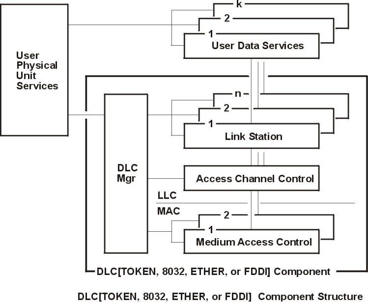
LLC refers to the manager, access-channel, and LS subcomponents of a generic data link control (GDLC) component, such as DLCTOKEN device manager, as illustrated in the DLC[TOKEN, 8032, ETHER, or FDDI] Component Structure figure.
Figure 1-4. DLC[TOKEN, 8032, ETHER, or FDDI] Component Structure. This diagram shows the component structure of the following four DLC device managers: DLCTOKEN, DLC8032, DLCETHER, and DLC FDDI. Each device manager has the same component structure with one exception: the DLC Component is named for the device manager it illustrates. The diagram has two parts: the components outside the DCL[TOKEN, 8032, ETHER, or FDDI] Component, and the components inside of it. Outside, the User Physical Unit Services connects to the DLC Manager on the inside and to the User Data Services on the outside. The diagram shows multiple (numbered from one to k) User Data Services, with the first connecting to the last. Each User Data Service connects to a corresponding Link Station, which connects to the DLC Manager. The diagram shows multiple (numbered from one to n) Link Stations, with the first connecting to the last. Each Link Station connects to a single Access Channel Control, which connects to the DLC Manager. The connection for Access Channel Control crosses the line from LLC to MAC to connect with two Medium Access Controls. The two Medium Access Controls connect with each other, then with the DLC Manager.
Each LS controls the transfer of data on a single logical link. The access channel performs multiplexing and demultiplexing for message units flowing from each LS and manager to the MAC. The DLC manager performs the following actions: